THINGS TO DO IN PUMP SELECTION
Capacity needed by the system where the pump is to be used should be determined in m³/h (meter cubic/hour) or (l/m) liter/minute.
Liquid viscosity is a very important factor for pump size, calculating pipe diameter, assignment of motor and redactor to drive the pump. Because of these reasons, viscosity of liquid during the transfer must be determined clearly. Various viscosity conversions are given herein below.
▷ Click to view the viscosity conversion table.
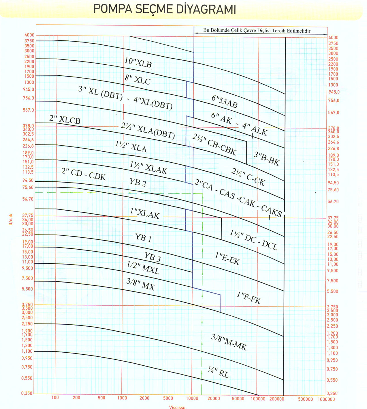
Pump size is determined from the following table by considering the capacity and viscosity determined before
▷ Click to view the pump selection diagram.
The type of pump is determined; After selecting the pump size from the table above; The type of the pump is determined by considering the requirements of the system. (Internal Eccentric Gear, Helical Gear etc.)
Maximum (positive suction) distance between pump axis and the liquid placed in tank is called as SUCTION DEPTH. This distance is specified by length of suction pipe, its diameter and elbows, filters and clacks on the pipe. Suction distance depends on the air pressure where system is located. Air pressure is accepted as 760 mm Hg or 10,33 mWc at the sea level. In practice this value may be taken as 10 mWc. As a result of pressure drop, suction distance decreases 10 cm per 100 meters climbed from sea level. In the other words suction distance of a pump at 1.000 meter is 1 meter shorter than the pump that was installed in the sea level and of a pump placed in 2.000-meter height shall be 2 meters shorter. Pump installed in 2.000 meters can suck the liquid from a distance averagely between 6 or 7-meter depth when losses in fitting materials etc. are taken into consideration. This distance may change depending on material density sucked and ambient temperature. In the cases when the pump shall operate for vacuum (suction); suction pipe diameter must be smaller than pump inlet mouth diameter and if it is possible a clack must be fastened to the suction line.
If the pump operates for forcing instead of sucking, it should be installed as close as possible to the tank and to the bottom verge of the tank. Suction pipe must be larger than pump inlet mouth diameter or with the same diameters.
The pipe diameter of force line of pump is determined depending on viscosity of liquid to be transferred, specific gravity and discharge distance (Table 8= pipe power loss depending on viscosity and capacity. Please consult our factory)
Power of the motor to drive the pump may change depending on capacity of liquid (l/h) transferred by the pump, opposite resistance (mss), specific gravity of liquid and productivity of the pump. Opposite resistance in pipes is accepted as 10mss for 100 meters in horizontal and 10 mss for 10 meters in vertical for liquids which of specific gravity is 1 and lower than 1. Load loss (opposite resistance) in pipes for liquids which of specific gravity is more than 1 is calculated by the following formula by using coefficients written in table 8.
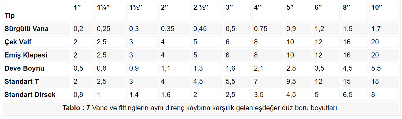
Note: When opposite resistance is calculated; equivalent pipes length of elbows, clacks, valves etc existing on the line should be considered too. Equivalent pipe lengths are given in table 7.
Motor power (hp) = capacity (l/h) x opposite resistance (mss) x specific gravity of liquid
3600 x 75 x pump yield
1 kW = 1,36 hp
 PIPE POWER LOSS TABLE DEPENDING ON VISCOSITY - CAPACITY- Click to download as Excel.
Materials to be used in the pump should differ by the product transferred by the pump. As we know that every liquid has different chemical and physical properties, thus its interaction with pump material differs. Henceforth, pump materials are selected according to the liquid. For instance, bushing of a pump used in transfer of a liquid having lubricant property is bronze; bushing of a pump used in transfer of a acid-origin liquid are is selected as carbon. Besides the surfaces in contact with liquid for the pumps realizing food transfer should be produced of stainless or teflon material. After pump material is determined; it shall decided whether the pump is jacketed or non-jacketed according to necessity to warm or to cool the liquid to run through the pump thereby the pump.
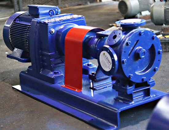
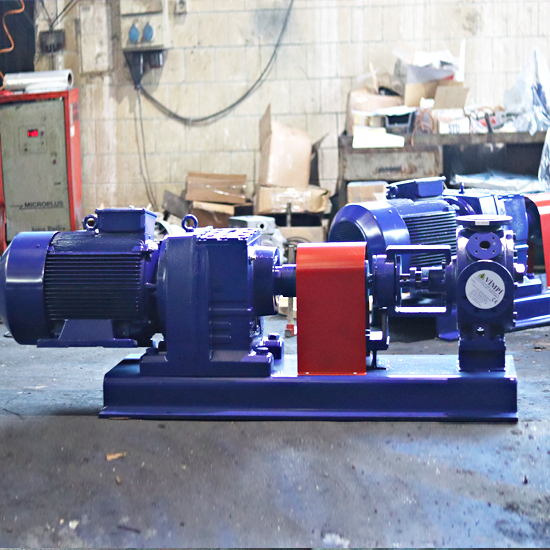
After all features of the pump is determined; finally pump driving way is decided.
Existing coupling shapes are as follows ;
- a. Not coupled. (Bare Pump)
- b. Coupled directly to the electrical motor
- c. Coupled to electric motor with reducer
- d. Coupled with reducer
- e. Coupled with belt pulley.
- f. Coupled to electric motor with variator reducer
- g. Coupled to pull-type (wheeled) chassis
- h. Coupled with belt pulley and reducer