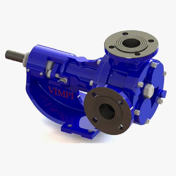
INTERNAL GEAR PUMPS
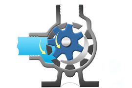
1- While ring gear (rotor) rotates in the direction of arrow by rotational motion taken from the motor, internal idler gear (star) diverges from the ring gear by rotation. The liquids fills in the empty space occurred by separation of the gears.
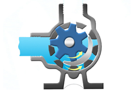
2- Crescent which is placed at pump cover and gears diverges from each other and the liquid is carried through gear clearances.
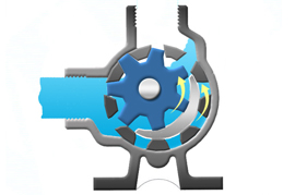
3- While ring gear and idler gear meshes each other, the liquid is discharged to delivery channel.
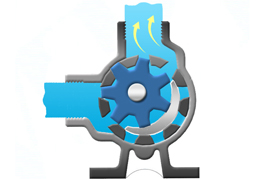
4- The liquid discharged to the delivery channel moves through the installation and the transfer process becomes realized.
INTERNAL GEAR PUMPS
Present the choice of preference at places up to 14 bars atmospheric pressure and for such viscous fluids as molasses, chocolate, asphalt, thick lubricants and even such materials that need to be slightly crushed, due to their large pitches and high tolerance between gears.
Internal gear pumps are consisting of two moveable parts and they have positive displacements. While the rotor gear coupled to pump shaft is turning, rotor gear will transmit the motion to the idler pin in order to rotate it. During this period idler pin and rotor separates each other by crescent and vacuum will occur.
Pump sucks the constant amount of liquid by the virtue of vacuum. Therefore, this sucked fluid flows from gear teeth spaces (clearances) to the discharge outlet.
While the gears meshing in the discharge outlet, pressure occurs and this motion allows the fluid transfer to the outside.
Meanwhile idler pin and rotor gear mesh each other in the discharge outlet and this activity reveal the pressure for forcing fluid to the outside. Pump transfers the liquid by every revolution of the shaft in accordance with volume capacity. Henceforth capacity of pump is directly proportional to its magnitude and RPM.
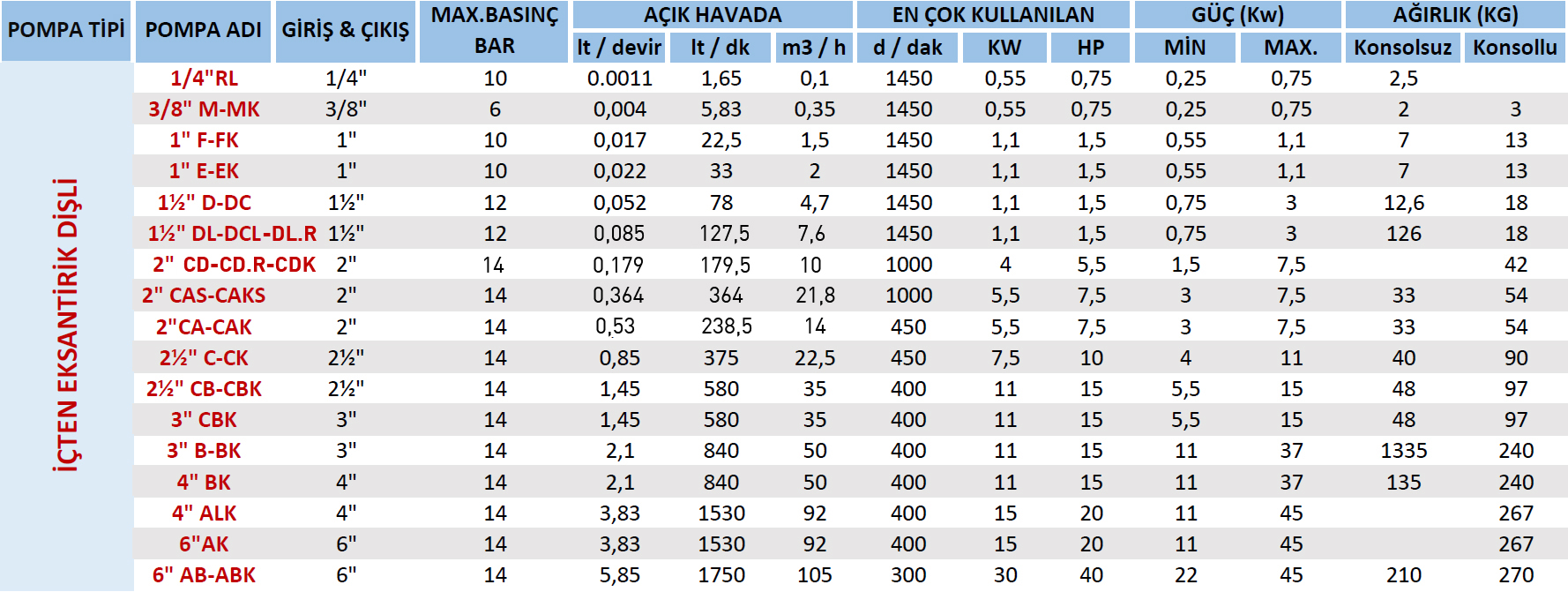
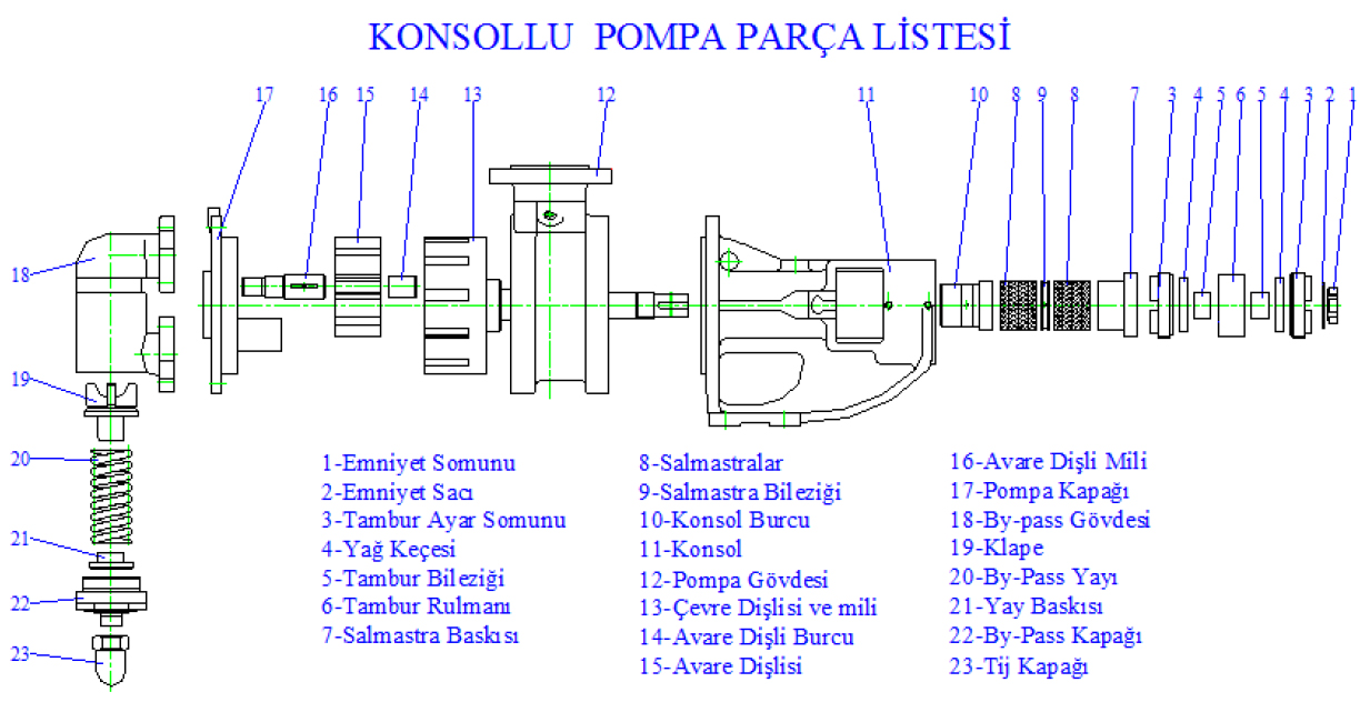
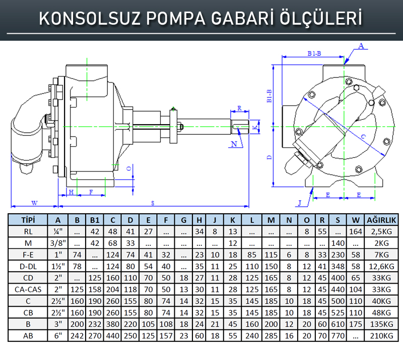
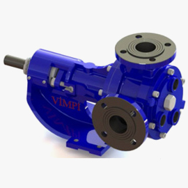
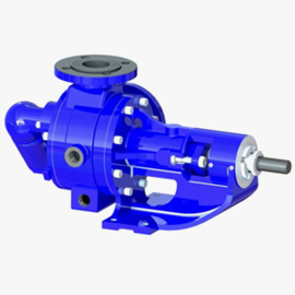
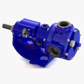
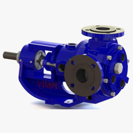
Internal gear pumps gather in two main groups as bracket pumps and non-bracket pumps (Table 12). Besides bracket provides possibility to convert into eight different position (45o interval) for easiness of mounting of inlet and outlet mounts in pumps and also provides opportunity to operate pumps long-life under heavy conditions since bushing of pump shaft is more rigid. Furthermore flow of the pump can be increased and decreased with specified ratio by the virtue of adjusting drum existing on the bracket (Table 13). Letter of (K) which is used to call our internal eccentric gear pumps means that it is bracket-pump. (For instance: 2” CA: Non-bracket pump, 2” CAK : Bracket-Pump)
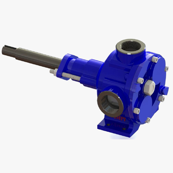
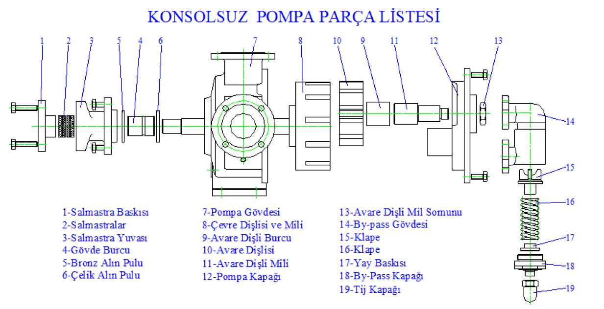
► With Non-Bracket Type Internal Gear Pump Spare Parts List
Internal gear pumps gather in two main groups as bracket pumps and non-bracket pumps (Table 12). Besides bracket provides possibility to convert into eight different position (45o interval) for easiness of mounting of inlet and outlet mounts in pumps and also provides opportunity to operate pumps long-life under heavy conditions since bushing of pump shaft is more rigid. Furthermore flow of the pump can be increased and decreased with specified ratio by the virtue of adjusting drum existing on the bracket (Table 13). Letter of (K) which is used to call our internal eccentric gear pumps means that it is bracket-pump. (For instance: 2” CA: Non-bracket pump, 2” CAK : Bracket-Pump)
@2021 Vimpi Viscous Liquid Pumps. All rights reserved.